FSAE Shutdown Circuit Guide
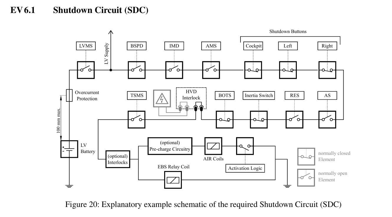
FSAE Shutdown Circuit (SDC): Complete Design Guide
Scope: Formula SAE Electric (EV) vehicles, with notes for Combustion (IC) where the rules overlap. Important: Rule numbers below follow the 2021 FSAE rules layout (T.3.2, EV.7.7, EV.8.x). Rule numbering and some thresholds are reorganized in later years and differ between FSAE, Formula Student (FSG/FSUK) and Formula Hybrid+Electric. Always verify against your competition's current rulebook.
Table of Contents
- What is the shutdown circuit?
- Design philosophy
- Architecture overview
- Component-by-component breakdown
- Master switches (GLVMS and TSMS)
- Shutdown buttons (BRBs)
- BOTS: Brake Over-Travel Switch
- Inertia switch
- BSPD: Brake System Plausibility Device
- IMD: Insulation Monitoring Device
- AMS / BMS
- Interlocks (HVD, TSMP access, etc.)
- Accumulator isolation relays (AIRs)
- Latching and reset behavior
- Wiring, fusing and power budget
- Startup sequence
- Fault matrix
- Technical inspection (scrutineering) checklist
- Common mistakes and failure modes
- Design and validation checklist
- Glossary
- Images and references
1. What is the shutdown circuit?
The Shutdown Circuit (SDC), also called the shutdown loop or safety loop, is a series chain of safety switches and monitoring devices that powers the coils of the Accumulator Isolation Relays (AIRs). If any element in the chain opens, the AIRs de-energize and the high-voltage (HV) Tractive System (TS) is disconnected from the accumulator.
In one sentence: the SDC is a hardware-enforced "dead man's chain" that guarantees the car's high voltage drops out whenever something unsafe is detected.
Key facts:
- It is a series circuit: every device must be "closed" for the circuit to stay closed.
- It operates on the GLV (Grounded Low Voltage) side (typically 12 V nominal, 24 V on some cars).
- It is fail-safe: loss of power, a broken wire or a failed component results in an open circuit, which means HV off.
- It is built from simple, mostly analog/mechanical parts so its behavior is deterministic and easy to inspect.
 Figure 1: Replace with your team's SDC schematic or the rulebook diagram (see Section 22).
2. Design philosophy
| Principle | What it means in practice |
|---|---|
| Fail-safe | Open circuit = safe state. Relays are normally open, so power must be deliberately applied to close them. |
| Series logic | Any single fault opens the loop. There is no voting and no bypass. |
| Hardware first | Critical functions (BOTS, BSPD, IMD, AMS outputs) must not depend on software that could hang. |
| Latching | Faults from the IMD and AMS stay latched until a manual reset (not by the driver). |
| Independence | The SDC must keep working even if the main ECU or VCU crashes. |
| Inspectable | Tech inspectors need to be able to trace and test each element. |
A shutdown circuit being open does not mean the car is safe to touch. The TS must still be verified de-energized with the TSMPs and discharge circuit.
3. Architecture overview
3.1 Typical series chain
GLV battery / DC-DC
      |
   [ GLVMS ]  ──► (powers entire GLV system)
      |
   [ Cockpit BRB ]
      |
   [ Left BRB ]
      |
   [ Right BRB ]
      |
   [ BOTS ]
      |
   [ Inertia switch ]
      |
   [ BSPD (relay/output) ]
      |
   [ IMD (relay/output) ]
      |
   [ AMS / BMS (relay/output) ]
      |
   [ Interlocks: HVD, etc. ]
      |
   [ TSMS ]   ◄── last switch before the AIRs (except precharge and interlocks)
      |
   [ AIR+ coil ] ── [ AIR- coil ]
      |
     GND
Order of the elements varies by team. The rules mandate what must be in the loop and a few ordering constraints (for example, the TSMS being the last switch before the AIRs), not a single layout.
3.2 Mermaid diagram
flowchart LR
    BAT[GLV Battery + DC/DC] --> GLVMS[GLVMS]
    GLVMS --> BRB1[Cockpit BRB]
    BRB1 --> BRB2[Left BRB]
    BRB2 --> BRB3[Right BRB]
    BRB3 --> BOTS[BOTS]
    BOTS --> INERTIA[Inertia Switch]
    INERTIA --> BSPD[BSPD]
    BSPD --> IMD[IMD]
    IMD --> AMS[AMS / BMS]
    AMS --> IL[Interlocks]
    IL --> TSMS[TSMS]
    TSMS --> AIRP[AIR+ coil]
    TSMS --> AIRN[AIR- coil]
    AIRP --> GND((GND))
    AIRN --> GND
3.3 Where each part lives on the car
| Device | Typical location |
|---|---|
| GLVMS, TSMS | Right side of the car, near the main hoop, at driver's shoulder height |
| Cockpit BRB | Within easy reach of the belted driver, near the steering wheel/dash |
| Side BRBs | Left and right of the car behind the driver, reachable by marshals |
| BOTS | At the brake pedal assembly |
| Inertia switch | Mounted rigidly to the chassis, usually near the driver's cell/accumulator |
| BSPD, IMD, AMS | In or near the accumulator container or low-voltage electronics box |
| Interlock switches | HVD connector, accumulator lid, TS enclosure covers |
 Figure 2: Car layout showing shutdown component placement.
4. Component-by-component breakdown
| # | Component | Purpose | Opens SDC when… | Reset |
|---|---|---|---|---|
| 1 | GLVMS | Kills all GLV power | Key turned OFF | Manual (key) |
| 2 | BRBs (x3) | Emergency stop | Button pressed | Manual pull/twist |
| 3 | BOTS | Detect brake failure/over-travel | Pedal exceeds normal travel | Cannot be reset by driver |
| 4 | Inertia switch | Detect crash | High deceleration | Manual reset |
| 5 | BSPD | Detect hard braking + high power | Plausibility violated | Manual (not driver) |
| 6 | IMD | Detect HV insulation fault | Insulation resistance below threshold | Manual (not driver) |
| 7 | AMS/BMS | Protect the accumulator | Cell over/under-voltage, over-temperature, over-current, comms loss | Manual (not driver) |
| 8 | Interlocks | Prevent HV with covers/connectors open | Connector unplugged or lid removed | Restoring the mechanical condition |
| 9 | TSMS | Master HV enable | Key OFF | Manual (key) |
5. Master switches (GLVMS and TSMS)
From the 2021 rules (EV.8.10), each car has two master switches.
5.1 GLVMS (Grounded Low Voltage Master Switch)
- Must completely stop all power to the GLV system.
- Located in the center of a red circular area, >50 mm diameter.
- Labeled "LV".
5.2 TSMS (Tractive System Master Switch)
- Must open the Shutdown Circuit.
- Must be the last switch before the AIRs (except precharge circuitry and interlocks).
- Located in the center of an orange circular area, >50 mm diameter.
- Labeled "TS" with the ISO 7010-W012 high-voltage symbol (black lightning bolt in a yellow triangle).
- Must support lockout/tagout.
5.3 Requirements common to both
- Direct acting: not through a relay or logic.
- Mounted on the right side, near the main hoop, at driver's shoulder height.
- Easily actuated from outside the vehicle.
- Rotary mechanical type with a red removable key, removable only in the OFF position.
- Rigidly mounted, not removed during maintenance.
- Rotary axis near horizontal and across the vehicle.
- ON position horizontal and clearly marked; OFF clearly marked.
 Figure 3: Master switch placement and marking.
6. Shutdown buttons (BRBs)
The "Big Red Buttons" are the emergency stops.
- A car needs three: one in the cockpit and one on each side of the car behind the driver.
- Red, clearly marked, mechanical, direct acting (they physically break the SDC current path).
- Typically push-to-open / twist-or-pull-to-reset.
- Must be reachable by track marshals without crossing the driver's space.
- Usually marked with a lightning/shutdown sign per the rulebook.
Design tips
- Use normally-closed (NC) contacts. A broken wire then equals an open SDC.
- Choose a button with a positive-opening contact block (contacts are forced apart).
- Check the contact rating for the SDC current plus inductive spikes.
7. BOTS: Brake Over-Travel Switch
From T.3.2:
- Installed so brake pedal travel beyond the normal range actuates it.
- A mechanical single-pole single-throw switch (push-pull or flip type).
- Operating it to OFF must:
- (IC) shut down the engine(s) and fuel pump(s).
- (EV) open the Shutdown Circuit.
- Repeated operation must not reset or restore power.
- The driver cannot reset it.
- Must be implemented with analog components, not PLCs, ECUs or similar digital controllers.
Why it exists: if a brake pedal, linkage or master cylinder fails and the pedal over-travels, the car must shut down immediately.
Design tips
- Mount the switch so it is actuated by the pedal itself or its mount, not a separate tab that can flex.
- Add a latch (a relay with a self-hold) if "repeated operation must not reset" is a concern, and confirm that approach with your rulebook.
- Test with the pedal fully extended and with a deliberately failed linkage.
8. Inertia switch
- Detects abnormal deceleration (a crash) and opens the SDC.
- Mounted with the correct orientation and torque, and in a place that experiences chassis loads.
- Needs a manual reset after triggering.
- Use a switch rated for the required g-level and confirm what the rulebook requires for your event.
Test: perform a bench "drop/shock" test and verify that it trips and stays latched.
9. BSPD: Brake System Plausibility Device
The BSPD is a standalone safety circuit that opens the SDC if the car is hard braking and delivering significant motor power at the same time.
9.1 What the rules require (2021 EV.7.7, summarized)
- Opens the SDC when both conditions are true for longer than a set time:
- Hard braking (brake pressure above a threshold, or equivalent).
- High motor power (above roughly 5 kW, measured by TS current).
- Reaction time is about 0.5 s of continuous implausibility.
- Must be analog/discrete logic. No microcontrollers or programmable logic in the decision path.
- Must latch and be resettable only manually, not by the driver.
- Must be tested during tech inspection (by simulating brake pressure and current signals).
- Must handle sensor fault detection (for example, a short to ground or to the supply on the brake pressure or current signals) and open the SDC.
Thresholds and timing change by year and competition. Check the exact numbers in your current rulebook.
9.2 Typical block diagram
flowchart LR
    BP[Brake pressure sensor] --> CMP1[Comparator: hard braking]
    CUR[TS current sensor] --> CMP2[Comparator: power > threshold]
    CMP1 --> AND[AND gate]
    CMP2 --> AND
    AND --> RC[RC timer ~0.5 s]
    RC --> LATCH[Latch]
    LATCH --> RELAY[SDC relay driver]
    SCS[Sensor short-circuit check] --> LATCH
    RELAY --> SDC[Shutdown circuit]
9.3 Design notes
- Use comparators (for example LM339-class) plus an RC timing network for the delay.
- Provide a sensor sanity check that flags a voltage outside the valid range (for example <0.5 V or >4.5 V on a 0.5-4.5 V sensor).
- Drive a normally-open relay through a low-side MOSFET. The relay only closes when everything is healthy.
- Document the thresholds, time constants and tolerances on your ESF (Electrical System Form).
- Provide test points and an inspection test procedure.
 Figure 4: BSPD architecture.
10. IMD: Insulation Monitoring Device
The IMD continuously monitors insulation resistance between the TS (HV) system and chassis/GLV ground.
10.1 Key requirements
- Must be a commercially available unit approved for the application (commonly the Bender IR155 series, or equivalent).
- Insulation threshold: typically ≥ 500 Ω/V of the maximum TS voltage.
- On fault, it must open the SDC and latch until manually reset.
- Must not be resettable by the driver.
- Connected to the TS with the correct measurement leads and chassis ground reference.
- Status output may drive an IMD indicator light visible to the driver and marshals.
10.2 Example
For a 600 V max accumulator voltage with a 500 Ω/V threshold:
R_min = 500 Ω/V × 600 V = 300 kΩ
The IMD must trip if insulation resistance falls below that value.
10.3 Design tips
- Keep IMD wiring short, and keep its ground reference connection solid.
- Make sure the IMD's output is fail-safe (a power loss results in an open SDC).
- Verify the startup self-test time and account for it in the startup sequence.
- Test with a known resistor (a "fault injection" resistor) from TS to chassis during validation.
11. AMS / BMS
The Accumulator Management System (battery management system) monitors the accumulator and opens the SDC on a fault.
11.1 What it monitors
- Cell voltages (over-voltage and under-voltage).
- Cell temperatures (over-temperature, and sometimes under-temperature for charging).
- Pack current (over-current).
- Communications loss between slave boards and the master.
- Sensor validity.
11.2 Requirements
- Must be able to open the SDC independently of the VCU.
- Fault must latch and not be driver-resettable.
- Provide a clear AMS fault indicator (light).
- Verify that all cells and temperature sensors required by the rulebook are monitored.
11.3 Design tips
- Add a hardware watchdog: if the BMS master stops sending "OK", the SDC opens.
- Use an independent safe output (a relay or an optocoupled "BMS OK" signal) into the loop.
- Keep thresholds in the cell manufacturer's safe limits, with margin.
12. Interlocks
Interlocks make sure HV cannot be enabled when it would be exposed or unsafe.
Common interlocks:
- HVD (High Voltage Disconnect) presence or position.
- Accumulator container lid closed.
- TS enclosure covers and TS connector mated.
- Segment maintenance disconnect (SMD) in place where used.
Interlock switches are usually in series in the SDC, near the TSMS. Use NC / positive-break switches so any unplug or open cover opens the loop.
13. Accumulator isolation relays (AIRs)
- Two relays (AIR+ and AIR-) isolate the accumulator from the rest of the TS.
- They are normally open, and their coils are powered only through the SDC.
- Open circuit SDC means AIRs open, so HV is disconnected from the TS.
- Precharge is performed through a resistor path before the second AIR closes, to limit inrush into motor controller capacitors.
Design considerations
- Contacts must be rated for the max TS voltage and fault current, including DC breaking capability.
- Fit flyback protection for the AIR coils (a diode, or the manufacturer's recommendation) without delaying the opening time unacceptably.
- Use auxiliary contacts for AIR weld detection and feed that to the controller.
- Economizer circuits (if used) must not allow the AIR to remain closed after the SDC opens.
13.1 Discharge circuit and discharge relay
When the SDC opens, the AIRs isolate the accumulator, but the motor controller / inverter DC-link capacitors (and any other TS capacitance on the load side of the AIRs) stay charged. The discharge circuit bleeds that voltage down so the car is safe to approach and work on.
What the rules require (2021 EV layout, summarized; verify the current numbers):
- After the SDC opens, the TS voltage on the load side of the AIRs must fall below 60 V DC within 5 seconds.
- The discharge circuit must be fail-safe: it must work when the SDC is open and when GLV power is lost or the GLVMS is OFF.
- It must be sized for the maximum TS voltage and be able to survive being connected at that voltage (a commonly quoted requirement is for at least 15 minutes).
- It must not be active in a way that interferes with normal operation or precharge.
- The design and discharge time must be documented on the ESF, and the discharge time is measured at tech inspection using the TSMPs.
Typical implementation: normally-closed (NC) discharge relay
 TS+ (load side of AIR+) ───┬─────────────┐
                            │             │
                         [ Motor        [ R_discharge ]
                          controller      │
                          capacitors]   [ Discharge relay, NC contacts ]
                            │             │
 TS- (load side of AIR-) ───┴─────────────┘

 Discharge relay COIL is powered from the SDC (same node as the AIR coils):
   SDC closed (HV allowed)  → coil energized → NC contacts OPEN  → no discharge path
   SDC open / GLV lost      → coil de-energized → contacts CLOSE → resistor bleeds the bus
flowchart LR
    SDC[Shutdown circuit closed] -->|coil energized| DR[Discharge relay contacts OPEN]
    DR --> RUN[Resistor disconnected, normal TS operation]
    SDC2[Shutdown circuit open / GLV lost] -->|coil de-energized| DR2[Discharge relay contacts CLOSED]
    DR2 --> BLEED[Resistor across TS bus, voltage falls below 60 V in under 5 s]
Because the relay is normally closed, any loss of power, broken coil wire or SDC trip results in the discharge path being connected. That is the fail-safe behavior inspectors look for.
Sizing the discharge resistor
The bus decays exponentially: V(t) = V0 · e^(−t / RC).
To reach 60 V in at most t = 5 s:
R ≤ t / ( C · ln(V0 / 60 V) )
Example: V0 = 400 V, C = 500 µF (total TS capacitance, including the inverter)
ln(400 / 60) = 1.897
R ≤ 5 / (500e-6 × 1.897) ≈ 5.27 kΩ
Pick a standard value well below the limit to cover tolerance and capacitance uncertainty (for example 2.2 kΩ to 3.3 kΩ). Then check the thermal side:
Initial power  P0 = V0² / R   = 400² / 3300 ≈ 48 W (peak, decays quickly)
Stored energy  E  = ½ C V0²   = 0.5 × 500e-6 × 400² = 40 J
- Choose a resistor rated for the voltage, the pulse energy, and repeated cycles (wirewound or aluminum-housed types are common).
- Mount it where it can dump heat and where a hot resistor can't damage wiring or the accumulator container.
- If the discharge is connected for a long time (for example, a relay that stays closed with the accumulator still connected through a failed AIR), the resistor must survive the continuous dissipation
V² / R. That is why the sizing is a trade-off: low R discharges faster but burns more power in a fault.
Discharge relay selection
| Parameter | What to check |
|---|---|
| Contact form | Normally closed, or a normally-closed contact block on a contactor |
| Voltage rating | Above max TS voltage, DC rating (not AC) |
| Breaking current | Resistor current at max voltage with margin (it also has to open at V0/R when it is energized) |
| Coil voltage | Matches the SDC voltage (12 V or 24 V) |
| Coil current | Include it in the SDC current budget (Section 15.2) |
| Pickup/dropout time | Must open before or as the AIRs close (see below) and close fast enough to meet the 5 s target |
| Isolation | Coil-to-contact isolation rated for the TS voltage |
| Mechanical | Vibration-rated, sealed, mounted inside the TS enclosure or accumulator container |
Timing with the AIRs and precharge
- At startup, the discharge relay must open before (or at the same instant as) the AIRs close and before precharge starts. Otherwise the precharge current is dumped into the resistor.
- Power the coil from the same SDC node as the AIR coils so they change state together.
- Verify on a scope: coil voltage vs. AIR contact state vs. bus voltage, for both startup and shutdown.
Alternatives (check that your rulebook and inspectors allow them)
- Motor controller internal active discharge: only if it is documented to meet the 60 V / 5 s requirement and still works with GLV off.
- Always-connected passive resistor: simple and fail-safe, but it wastes power continuously and drains the accumulator through the load-side bus when the AIRs are closed. Usually a poor trade-off for efficiency and heat.
- Solid-state (MOSFET) active discharge: possible, but the gate drive must be fail-safe (default ON when power is lost). More complex to justify at inspection.
Discharge-related failure modes
| Failure | Effect | Mitigation |
|---|---|---|
| Relay contacts stuck open | No discharge, voltage stays high | Use a NC relay, test discharge time regularly, monitor bus voltage |
| Coil powered through a path that survives GLVMS OFF | Discharge stays disabled when it should be active | Power the coil only from the SDC, never from an always-on rail |
| Resistor too large | Fails the 5 s requirement | Size using the formula with margin, measure it |
| Resistor too small / underrated | Overheating or burnt resistor | Check pulse energy and fault-case dissipation |
| Relay closes during precharge | Precharge fails or overheats the resistor | Verify timing, power the coil from the SDC node |
| Capacitance underestimated (bigger inverter, extra filters) | Discharge slower than calculated | Re-measure after any hardware change |
Test procedure (bench and tech inspection)
- Bring the TS up to the operating voltage (use a reduced voltage first during bench testing).
- Measure at the TSMPs with a scope or a data-logging meter.
- Open the SDC (press a BRB) and record the time for the voltage to fall below 60 V.
- Repeat with: GLVMS OFF, TSMS OFF, and IMD/AMS fault.
- Confirm the discharge resistor temperature after repeated cycles.
14. Latching and reset behavior
| Device | Latching required? | Who can reset? |
|---|---|---|
| IMD | Yes | Manual reset, not the driver |
| AMS | Yes | Manual reset, not the driver |
| BSPD | Yes | Manual reset, not the driver |
| BOTS | Must not reset by repeated operation | Cannot be driver-reset |
| BRB | Mechanically latched | Pull/twist to reset |
| Inertia switch | Latched | Manual |
Reset hardware is typically a dedicated button or key-switch accessible from the outside of the car, or a pit-side reset only accessible to team members.
Do not wire any reset through the driver-accessible steering wheel or dash.
15. Wiring, fusing and power budget
15.1 Wiring practice
- Use automotive-grade wire (for example, TXL/GXL), a gauge suited for the loop current, and proper crimps with strain relief.
- Keep SDC wiring segregated from TS HV wiring and from noisy motor/inverter wiring.
- Use locking connectors (Deutsch, Molex MX150 or similar) with pin-lock and clear labeling.
- Use a distinct wire color for the SDC (many teams choose a dedicated color so it can be traced quickly).
- Avoid splices; terminate on terminal blocks where possible.
15.2 Power budget
The loop carries only the AIR coil current plus the relay coils of BSPD/IMD/AMS. Typical total is a few amps.
Example:
| Load | Current @ 12 V |
|---|---|
| AIR+ coil | 0.4 A |
| AIR- coil | 0.4 A |
| BSPD relay | 0.1 A |
| IMD relay | 0.1 A |
| AMS relay | 0.1 A |
| Total | ~1.1 A |
- Size the fuse and switch contacts with margin (>2x).
- Many rulebooks require you to list SDC current draw on the ESF.
15.3 Fusing
- Fuse the SDC supply near the source.
- Make sure fuse rating protects the wiring but doesn't nuisance-trip on relay inrush.
16. Startup sequence
Typical sequence for an EV:
- GLVMS ON: GLV system powers up (BMS, IMD, VCU, BSPD).
- IMD and BSPD self-checks complete, and fault indicators clear.
- BMS reports OK (cells in range, comms alive).
- All BRBs released, BOTS and inertia switch closed.
- TSMS ON: the SDC loop closes and the AIR coils get power.
- Precharge runs; when the voltage reaches the target, the second AIR closes.
- TS active indicator turns on.
- Ready-to-Drive (RTD) sequence: brake pressed + start button, then the RTD sound plays (about 1-3 s) before the motor controller is enabled.
sequenceDiagram
    participant D as Driver/Team
    participant G as GLVMS
    participant S as SDC
    participant T as TSMS
    participant A as AIRs
    participant P as Precharge
    participant R as RTD
    D->>G: Turn ON
    G->>S: GLV power available
    S->>S: IMD / BSPD / BMS checks pass
    D->>T: Turn ON
    T->>A: Coil power (via SDC)
    A->>P: AIR- closed, precharge starts
    P->>A: Voltage reached, AIR+ closes
    D->>R: Brake + Start button
    R->>D: RTD sound, drive enabled
17. Fault matrix
| Fault | Detector | SDC result | Driver indication | Recovery |
|---|---|---|---|---|
| Insulation fault | IMD | Opens, latched | IMD light | Fix insulation, manual reset |
| Cell over-temperature | AMS | Opens, latched | AMS light | Cool down, inspect, manual reset |
| Brake pedal over-travel | BOTS | Opens | None (car stops) | Repair brake system |
| Brake + throttle plausibility | BSPD | Opens, latched | BSPD indicator (if fitted) | Resolve cause, manual reset |
| Crash | Inertia switch | Opens | None | Inspect car, manual reset |
| Emergency stop | BRB | Opens | None | Release the BRB |
| HVD removed / lid open | Interlock | Opens | None | Restore the connector or lid |
| GLV power loss | n/a | Opens (relays de-energize) | Dash dark | Restore power |
| Any SDC opening | Discharge relay (NC) | Contacts close, TS bus bleeds below 60 V in under 5 s | TS active light off | Verify with TSMPs before touching |
18. Technical inspection checklist
Typical items inspectors check (confirm with your event):
- SDC schematic submitted on the ESF and matches the car.
- GLVMS and TSMS: location, color, labeling, key, direct-acting.
- All three BRBs in place and working.
- BOTS operates and cannot be reset by repeated operation.
- Inertia switch present, correctly mounted.
- BSPD tested using the inspection procedure (simulated brake + current).
- IMD tested with a known fault resistor.
- AMS fault test (for example, disconnect a sense wire or simulate over-temperature).
- Interlocks open the SDC.
- All SDC elements are in series with no bypass.
- No programmable logic in the parts where it is prohibited.
- Latching and reset behavior verified.
- TS active light and fault lights are working.
- Discharge circuit: discharge relay is normally closed, coil powered only from the SDC, TS < 60 V within 5 s after SDC opens (also with GLVMS OFF).
- TSMP voltage checks after SDC open.
19. Common mistakes and failure modes
| Mistake | Consequence | Fix |
|---|---|---|
| Normally-open switches used where NC are needed | A broken wire reads as "OK" | Use NC contacts so a broken wire opens the loop |
| Software-only BSPD | Fails inspection, unsafe if code hangs | Implement analog/discrete logic |
| BRB wiring routed through a connector without positive locking | Intermittent shutdowns | Use locking connectors and strain relief |
| IMD ground reference poor | False trips or missed faults | Short, solid chassis ground connection |
| Reset accessible to the driver | Rule violation | Move reset to an external/pit location |
| Relay coil without flyback protection | Voltage spikes damage electronics | Add diodes or snubbers |
| AIR economizer keeps AIR closed after SDC opens | Dangerous | Verify timing, test with a scope |
| Under-rated BRB/inertia contacts | Contact welding | Use contacts rated for the current and inductive load |
| Missing BMS watchdog | A BMS crash leaves the SDC closed | Add a hardware watchdog |
| Undocumented thresholds | ESF mismatch at inspection | Record values and tolerances |
20. Design and validation checklist
Design
- Write a requirements list straight from the rulebook (with rule numbers).
- Draw the full SDC schematic with every element, rating and connector.
- Do a fail-safe review (FMEA): for each wire, connector and component, what happens when it opens or shorts?
- Define thresholds and timing (BSPD, IMD, AMS).
- Choose parts with margin (current, voltage, temperature, vibration).
- Plan test points, indicators and reset hardware.
Bench validation
- Continuity and polarity check of the full loop.
- Trip each element individually and confirm the SDC opens.
- Measure AIR opening time after an SDC trip.
- BSPD: sweep brake pressure and current, confirm thresholds and delay.
- IMD: inject a fault resistor, confirm trip and latch.
- AMS: simulate over-voltage, under-voltage, over-temperature and comms loss.
- Vibration/connector wiggle test while monitoring SDC voltage.
Vehicle validation
- Rain/water exposure check on switches and connectors.
- Full startup/shutdown cycles (10+).
- Verify the TS discharge and TSMP readings after every shutdown path.
- Run a mock tech inspection with someone outside the electrical team.
21. Glossary
| Term | Meaning |
|---|---|
| SDC | Shutdown Circuit |
| GLV | Grounded Low Voltage system (all non-tractive systems) |
| TS | Tractive System (high voltage) |
| GLVMS | Grounded Low Voltage Master Switch |
| TSMS | Tractive System Master Switch |
| BRB | Big Red Button (emergency shutdown button) |
| BOTS | Brake Over-Travel Switch |
| BSPD | Brake System Plausibility Device |
| IMD | Insulation Monitoring Device |
| AMS / BMS | Accumulator / Battery Management System |
| AIR | Accumulator Isolation Relay |
| TSMP | Tractive System Measurement Points |
| HVD | High Voltage Disconnect |
| Discharge relay | Normally-closed relay that connects the discharge resistor across the TS bus when the SDC opens |
| ESF | Electrical System Form |
| RTD | Ready To Drive |
| SSOK | Safety Systems OK |
22. Images and references
22.1 About the image links
The image placeholders above (for example images/sdc_overview.png) are local paths. I could not verify stable direct image URLs, and I don't want to give you broken or invented links. To fill them in:
- Save screenshots/diagrams into an
images/folder next to this file, or - Replace each path with a direct image URL you have rights to use, for example:

Best sources for diagrams:
- Your rulebook's own schematic figures (for example, the "Shutdown Circuit Schematic" figure in the EV section, or the Formula Hybrid+Electric ESF-2 form figures such as the Safety Shutdown Circuit Schematic and Location of Shutdown Circuit Components).
- Your team's own CAD/schematics (best option, since it is your actual car).
22.2 Web references (pages with diagrams and explanations)
- Columbia FSAE rules mirror, BOTS (T.3.2): https://fsae.engineering.columbia.edu/FSAE_Rules_2021_V1_files/part220.htm
- Columbia FSAE rules mirror, Master Switches (EV.8.10): https://fsae.engineering.columbia.edu/FSAE_Rules_2021_V1_files/part374.htm
- Open-source BSPD design (KiCad, discrete analog): https://github.com/aditeyadc/bspd
- Hanze Racing Division shutdown circuit overview: https://www.eurocircuits.com/student-projects/hanze-racing-division-and-their-driverless-electric-race-car/
- Academy Racing Team shutdown circuit system overview: https://academyracingteam.duckdns.org/books/low-voltage/page/system-overview
- Northeastern Electric Racing electrical glossary: https://nerdocs.atlassian.net/wiki/spaces/NER/pages/136085511
- Formula Hybrid+Electric ESF-2 (Electrical System Form): https://docs.google.com/document/d/1TNi1OnET5XftBq-qFznYSoukxCc8o6MC/export?format=pdf
22.3 Suggested figures to create
| Figure | Content |
|---|---|
| Fig. 1 | Full SDC schematic (series chain) |
| Fig. 2 | Car layout with component locations |
| Fig. 3 | Master switch mounting and labeling |
| Fig. 4 | BSPD block diagram and thresholds |
| Fig. 5 | IMD wiring (TS+, TS-, chassis reference, output) |
| Fig. 6 | AIR + precharge circuit |
| Fig. 7 | Startup state diagram |
Document status: draft. Cross-check every rule number, threshold and timing with the current official rulebook for your competition and year.